All pixels of a color filter array block appear with the same color. The red component is from the red pixel of that block, the blue component is from the blue pixel and the green component is the average of the two green pixels.
Only one pixel per color filter array block is shown in reduced size display mode, it's color is calculated according the rules described above.
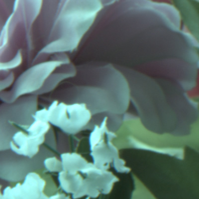
Left is a part of an image displayed in composite mode, normal size.
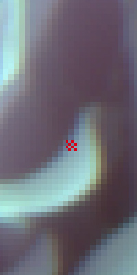
Right is a crop 4x magnified, showing, that the pixels in 2x2 blocks have the same color; the red pixel grid demonstrates the pixel
size
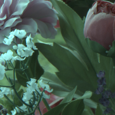
Left is a part of an image displayed in composite mode, reduced size.
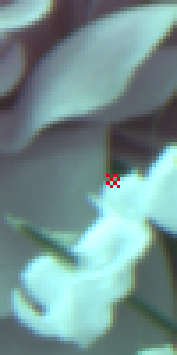
Right is a crop 4x magnified, showing, that the pixels have individual colors; the red pixel grid demonstrates the pixel size
-
Channel related color mode, shortcut: Ctrl-N.
Each pixel is displayed with the color and intensity of the corresponding raw pixel. This display is the closest to how one can imagine the raw pixels. Reduced size display is not supported in this mode.
The color selection checkboxes can be checked/unchecked in this mode. If a color is selected in the black and/or white group, that color is included in the display, otherwise all those pixels remain black.
This display mode allows for a more "close" examination of the image on pixel level than the composite color mode, as the pixels are displayed on their own, without mixing them with their neighbors, but the intensity of the displayed pixels allows for good image recognition, in contrast to the exposure display mode.
The sharpness of an image and fine details can be judged this way better than in other modes; an example for the usage is the comparison of images created with different lenses.
Identifying the effect of clipping too is easier in channel related display, when not all pixels of the color filter array blocks are clipped.As two green pixels, but only one red and one blue are displayed for every color filter array block, such an image is typically greenish, even if correctly white balanced. Furthermore, this display is darker than the composite color display, because two color components of every pixel are always 0.
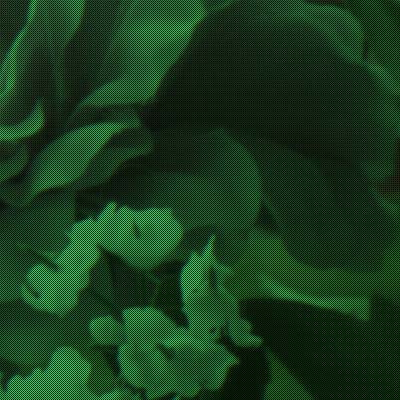
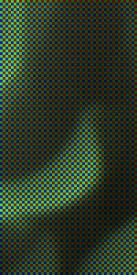
Left is a part of an image displayed in channel mode, all colors enabled.
Right is a crop 4x magnified, showing, that each pixel is either red or green or blue. The intensity is according to the raw pixel value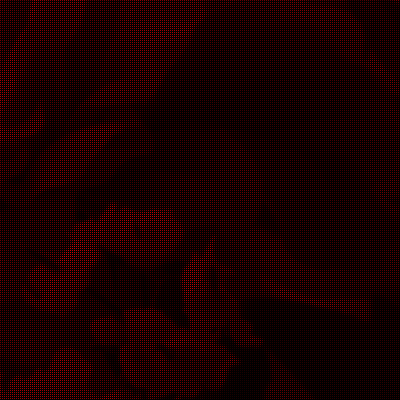
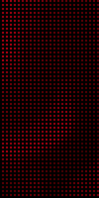
Left is a part of an image displayed in channel mode, only the red channel is enabled.
Right is a crop 4x magnified, showing, that three pixels out of four (the blue and the two greens) are not displayed -
Greyscale mode, shortcut: Ctrl-B.
In normal size display mode each pixel of a color filter array block is displayed as grey with the intensity according to that raw pixel value.
In reduced size display mode one grey pixel per color filter array block is displayed, with the intensity corresponding to the average of the raw pixel values.
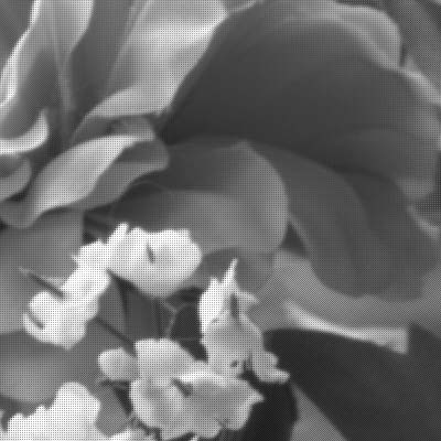
Left is a part of an image displayed in grey scale mode, normal size.
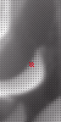
Right is a crop 4x magnified, showing, that the pixels in 2x2 blocks have the same intensity; the red pixel grid demonstrates the pixel size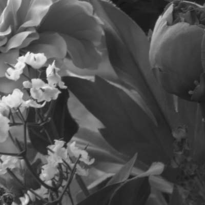
Left is a part of an image displayed in grey scale mode, reduced size.
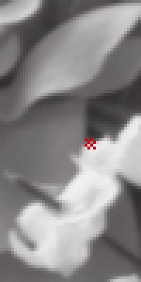
Right is a crop 4x magnified, showing, that the pixels have individual intensities; the red pixel grid demonstrates the pixel size
The effects of settings
It is most important to understand the role of the settings in the process of converting the raw pixel value in the RGB value. The effects of the settings/selections are the same in the three image display modes, and the same effects are reflected by the histogram of mapped data.
-
Black level
Some cameras' raw images include several rows and/or columns of pixels outside the captured image as well; these are called masked pixels. Their values show the effect of the so-called black current, that part of the pixel value, which is not caused by the captured light.
Other cameras record one or more direct values indicating the black levels.The pixel values of the image have to be corrected by the calculated values, depending on the pixel's position (typically with Canon cameras), or with the recorded correction value. Other cameras do not record any information for this purpose, rather they record the corrected pixel values.
The process described above is called the black level correction.
The initial value of Black point is the minimum of the black level correction values, if there are any, zero otherwise. However, this is only for orientation; when carrying out the black correction, the program always calculates with the pixel-related value, not with the minimum.
The minimum, maximum and average of the correction values are shown with the histogram display.
The first step of the conversion is substracting the respective black level correction value from the original pixel value. A negative result will be replaced by zero (yes, it can happen that the black level correction is higher than the pixel value).
In case the resulting value is zero, black clipping is said to have occured on raw level. "Clipping" in this sense is not a generally accepted term, but this is analogous to the clipping of highlights in the sense, that the value 0 represents all smaller values, which could not be recorded.
If the Raw clipping checkbox is checked, the black-clipped pixels will be displayed with the RGB value 255, or in case of composite color it contributes to the resulting color with 255. If the raw clipping option is not selected, such pixel values are converted to the RGB value 0, respectively they contribute to the composite color with 0.
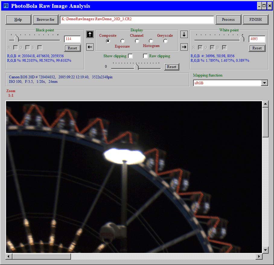
This night shot is obviously far underexposed; but how badly?
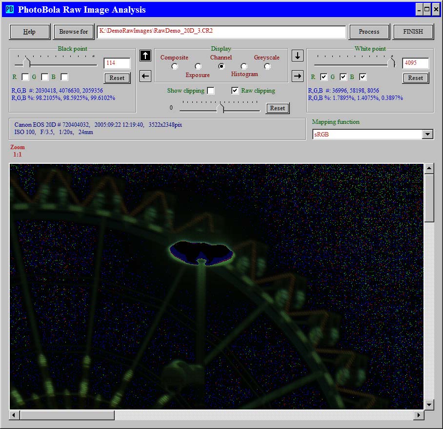
The raw clipping indication shows, that the entire sky is underexposed; however, that's not bad, as nothing interesting could be found there. The lamp is overexposed into clipping, but that can be accepted
-
Black point
The result of the black level correction is an absolute pixel value, starting with 0. An adjustment can be applied to either increase the absolute values, or to clip them at a certain level; this adjustment is the black point setting.
If the black point is lower than the minimum of the black levels, then all absolute pixel values will be increased by the difference between the black point and the minimum of black levels. This causes the image to appear lighter; however, the relative differences between the pixels become less, i.,e. the contrast decreases.
Obviously, this can not happen if black level correction does not apply.If the black point is higher than the minimum of the black levels, then all absolute pixel values will be reduced by the difference between the black point and the minimum of black levels. If black level correction does not apply, then the black point itself is the "clipping point".
This adjustment causes the image to appear darker, and details may be lost, as all pixel values between 0 and the black point will become "equalized", this is induced clipping, as opposed to raw clipping.
If the Show clipping checkbox is checked, then the pixels clipped by the black point but not clipped at the raw level will be displayed with the RGB value 255, or in case of composite color it contributes to the resulting color with 255. If the Show clipping option is not selected, such pixel values are converted to the RGB value 0, respectively they contribute to the composite color with 0.
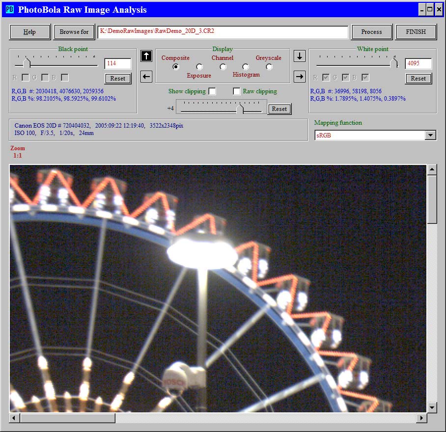
Increasing the lightness by 4 EV exaggerates the noisiness, this way it can be judged better
L'augmentation de 4EV a été obtenue avec le curseur non labelisé juste en-dessous des cas "Clipping" (cf ci-après)
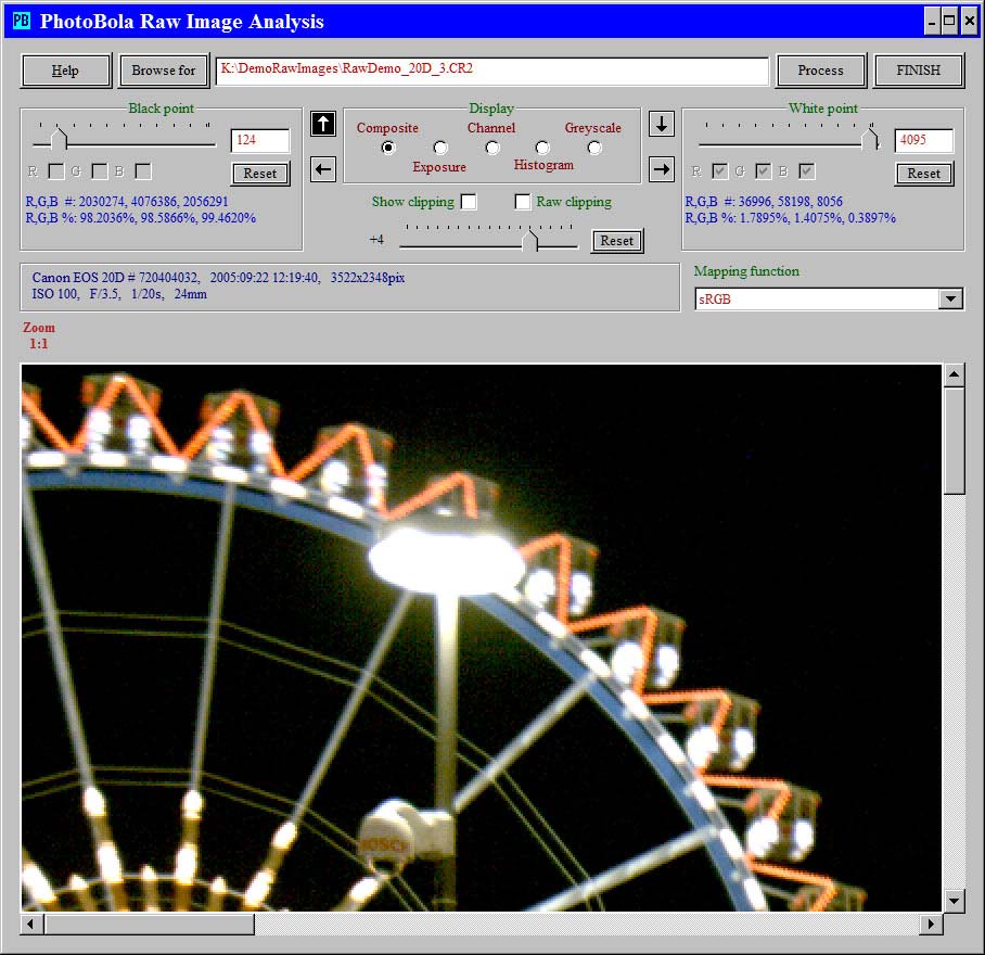
Increasing the black point by only ten levels makes the noise invisible
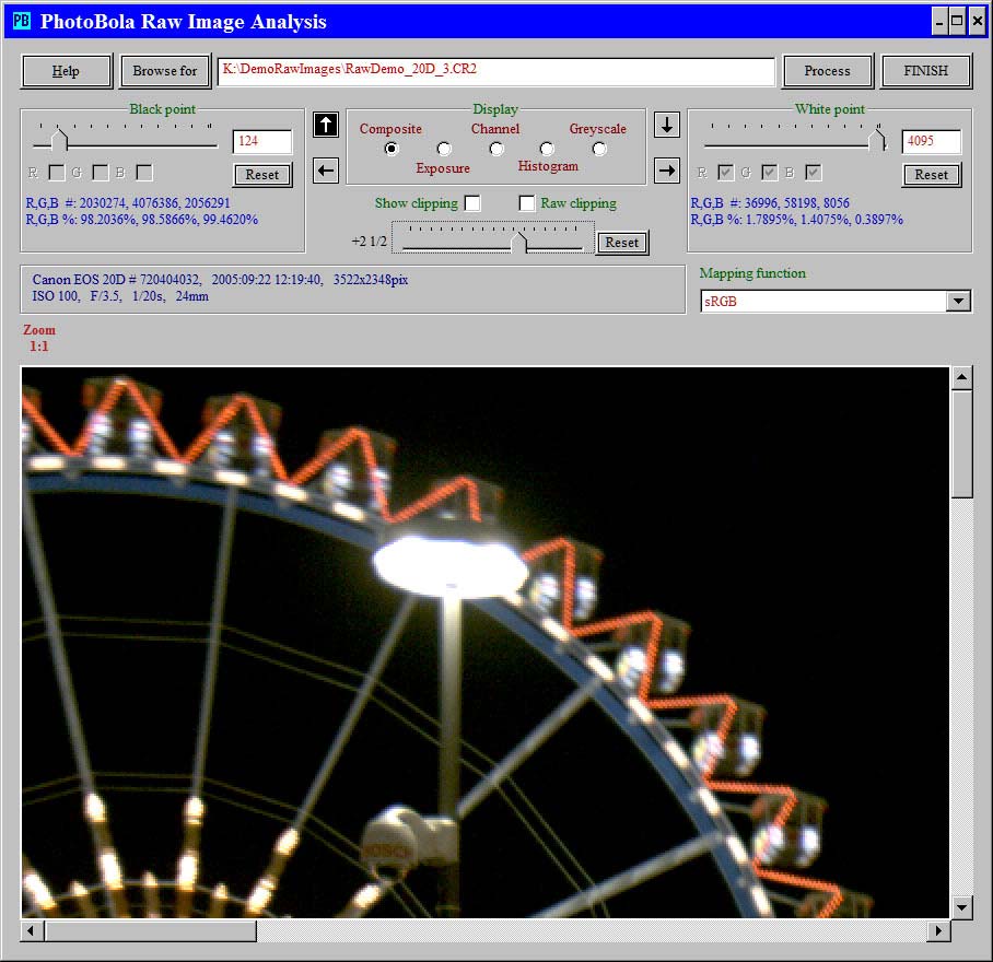
Going down with the lightness increase to 2.5 EV while keeping the black point adjustment proves, that this shot is not totally lost
-
Pixel saturation
The pixels of some cameras can reach the maximum value representable with the given bit depth; for example the pixel values of the Canon 20D can reach 4095. Other cameras' pixels may clip at a lower level; the clipping level may depend on the ISO, on other factors, even on the particular copy of the camera model. It often depends on the channel (pixel color); even differences between the two green positions within the color filter array are not seldom. Some cameras' pixels (sometimes only certain channels) do not clip at a single level, but in a level range; this is the range of non-linearity. The pixels have to be regarded as clipped from the lower limit of this range, because the values within the range do not represent meaningful information about the image.
If the original (i.e. not black level corrected) pixel value is equal to or greater than the respective clipping level, then that pixel is said to be raw clipped. If the Raw clipping checkbox is checked, the clipped pixels will be displayed with the RGB value 0, or in case of composite color it contributes to the resulting color with 0. If the Raw clipping option is not selected, such pixel values are converted to the RGB value 255, respectively they contribute to the composite color with 255.
The current version of Rawnalyze contains the clipping levels of most supported cameras hard coded; however, those values may not be accurate with all copies of that particular camera model. This may lead to reporting raw clipping, when it did not occur, or not reporting actual clipping.
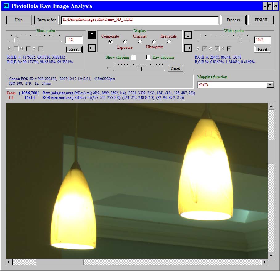
The lamp shades appear too bright; did clipping occur?
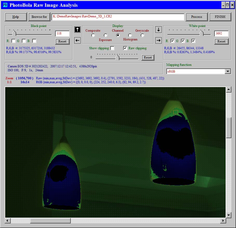
Turning on the raw clipping indication shows, that in fact some clipping occured. The effect is best visible in channel mode
Keep in eyes, that the clipping indication shows, which colors did not clip, because the clipped pixels are substituted by 0:
- the blue color indicates, that red and green clipped,
- the black shows, that all three colors clipped,
- the small greenish patches are suspicious; green indicates, that the red and blue clipped, but is this really green?
The statistics of the selection in one of the patcher (marked with an orange rectangle) proves, that the blue was in fact far from clipping, but some green pixels came very close to that.
-
White point
The white point specification, reduced by the current black point value sets an upper limit to the pixel values after black level correction and the application of the white balance and lightness adjustment factors. Thus the white point induces a clipping based on adjustments, as opposed to the raw clipping.
Reducing the specified white point by the black point is necessary, so that the white point value can be regarded relative to the uncorrected raw pixel values. Thus the white point gets "black point adjusted" in certain sense. If a pixel is not clipped on the raw level and the adjusted pixel value is equal to or higher than the white point and the Show clipping checkbox is checked, the clipped pixels will be displayed with the RGB value 0, or in case of composite color it contributes to the resulting color with 0. If the Show clipping option is not selected, such pixel values are converted to the RGB value 255, respectively they contribute to the composite color with 255.
Thus a pixel can show up as clipped only in response to one of the clipping indication options, not both.
The initial value of the white point is either
- the highest of the saturation/non-linearity levels of the pixels, if available,
- the white level specification from the descriptive data of the raw file,
- the maximum possible pixel value according to the bit depth of the sensor.
Decreasing the white point can induce clipping and it generally increases the contrast and lightness of the displayed image. Increasing the white point causes the image appear darker and less contrasty, but it may be necessary to avoid induced clipping, which can be caused by whute balancing and lightness adjustment. Turning on-off-on-off the clipping indication (by checking-unchecking the respective box) makes the affected pixels appear alternatingly very bright and very dark; this way it is easy to spot the affected areas.
Thus a pixel can show up as clipped only in response to one of the clipping indication options, not both.
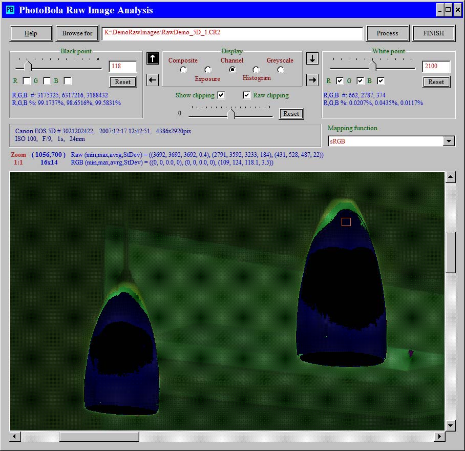
Decreasing the white point down to 2100 from 3692 lightens the image a lot and increases the contrast - but the clipped area too is larger now
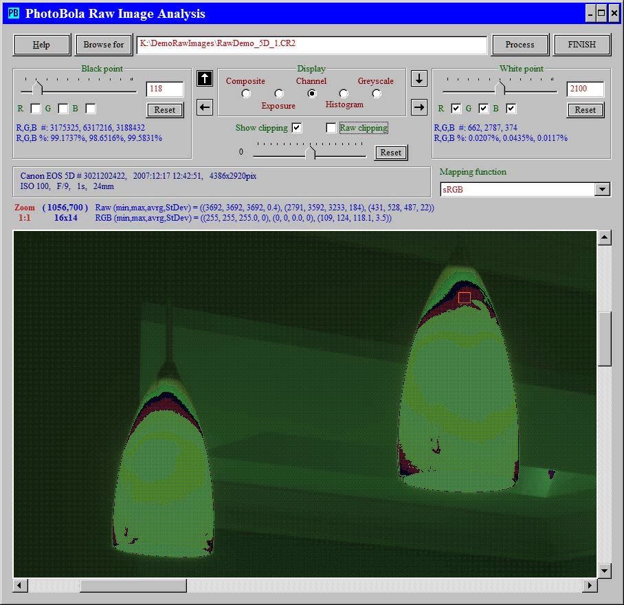
By turning off the raw clipping indication but keeping the induced indication on shows the effect of the clipping caused by reducing the white point becomes visible
Keep in eyes, that the clipping indication shows, which colors did not clip, because the clipped pixels are substituted by 0:
- the blue color indicates, that red and green clipped (but the blue is very dark, that was far from clipping),
- the yellowish color shows, where the blue clipped,
- red shows, that both the green and blue clipped,
- the greenish spots here too show red clipping,
- the tiny magenta spot on the ceiling is the sign of green clipping.
-
White balance
The color appearance of light reflecting objects depends on the light source. Sunlight midday, sunlight at the evening, cloudy day, indor lighting with halogen or non-halogen incandescent bulbs, fluorescent light, flashlight, etc. make objects appear in different colors. Additionally, the environment influences the light as well: the reflection from water surfaces, from the side of a forested mountain, from the colored walls of a room, etc. change the light falling on the objects.
In order to display colors like those of the actual scenery, the raw pixel values have to be adjusted relatively to each other, depending on the pixel filter color. This occurs via the multiplication of all black level adjusted pixel values of a channel by a coefficient depending on the sensor and the light source; this is called white balancing.
Some raw processors input and display the white balancing parameters in terms of temperature and tone adjustment. Rawnalyze keeps the parameters of white balancing in form of coefficients: one for the red channel, one for the blue channel and two coefficients for the green channel, seperate values for the two positions of the green pixels of the color filter array blocks. The coefficients will be applied when constructing the image display, and when displaying the mapped histogram and the Apply WB checkbox is checked.
The exposure display is affected only by a zero coefficients: that color is excluded from the display. This is interesting only as a way to exclude one of the green channels.
The current coefficients are displayed with the histograms:
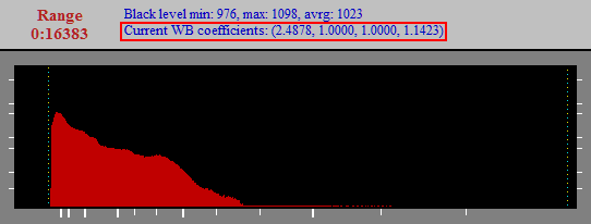
The first value, in this case 2.4878 is the coefficient for the red pixels, the second and third values, here 1.0000 are the coefficients for the green pixels, and the fourth value, in this example 1.1423 is the the coefficient for the blue pixels. The coefficient of the channel in which the highest raw pixel values occur will be 1.0000 (that is the green in most cases), and the other coefficients are selected such way, that they "equalize" the respective pixels in the selected area with the unchanged pixels.
The raw file usually contains a suggestion recorded by the camera for these coefficients; however, the current version of Rawnalyze does not take such specifications into account. The initial white balancing coefficients are all 1.0000, i.e. white balancing does not take place. Rawnalyze offers two methods to carry out white balancing after having read and interpreted the image data:
-
White balancing through selection
If there is a spot in the image, which should appear white or grey, then a selection has to be made in that spot. The pixels in the selected area are used for the calculation of the coefficients by the keyboard action Ctrl-W. The evaluated values become immediately active.
Note, that the two green coefficients are always set to the same value by this method.
-
White balancing in a dialog
There is a more sophisticated way to define the coefficients directly, i.e. without selecting a white/grey area in the image, namely in the white balancing dialog. That dialog can be started by the keyboard action Alt-Ctrl-W; it appears in its own small window. The currently active coefficients are displayed initially and then they can be changed. The changes made in that dialog become immediately effective, the result can be viewed in the original dialog, which can be activated by clicking on its window (the white balancing dialog window can be moved out of the way).

The two green channels are initially linked; the value of the first green channel applies to the second one as well. By clicking on the Green 2 button the slider and input field for the second green channel becomes enabled and its value becomes independent from the first green channel
The coefficients can be changed by the sliders in steps of 0.05; the change becomes effective immediately. Alternatively, the values can be entered in the input field (then it can be more accurate than 0.05). The entered value becomes effective when the Enter/Return key is pressed (the control remains in that input field), or by the Tab key, which then passes the control to the next input field or to the Accept button.
The entered value must be between 0.0000 and 4.0000. Entering zero "disables" the respective color; this is particularly interesting in exposure display mode: the two green channels can be separated this way.
The Reset button changes the respective value to 1.0000.
The Save button records the currently displayed coefficients in one of the numbered registers. The Recall button reinstates the coefficients of the respective register. These registers preserve coefficients past the lifetime of this dialog. Before registering a setting, all coefficients are 1.0000; thus the white balancing can be inactivated by using a register, which has not been loaded yet.
The Accept button saves the currently active coefficients and closes the dialog.
The Cancel button reinstates the coefficients, which were active when the dialog has been started, and closes the dialog. The coefficients saved in the registers remain preserved.
The five sets of coefficients are accessible outside the white balancing dialog as well: the currently active coefficients can be saved via the keyboard action Ctrl-Shift-1 or Ctrl-Shift-2 or Ctrl-Shift-3 or Ctrl-Shift-4 or Ctrl-Shift-5 in the respective register. The coefficients of a register can be activated any time via the keyboard action Ctrl-1, Ctrl-2, Ctrl-3, Ctrl-4 or Ctrl-5.
The coefficients are reset to 1.0000 when an image is read; however, the registers keep the recorded coefficients. Thus the same coefficients can be used in the analysis of several images.
Cette façon de faire est très primitive, mais le logiciel ne prétend pas être un vrai dérawtiseur. En fait une balance de blancs réalise un mélange 3x3 des couches, et non pas une simple transformation diagonale
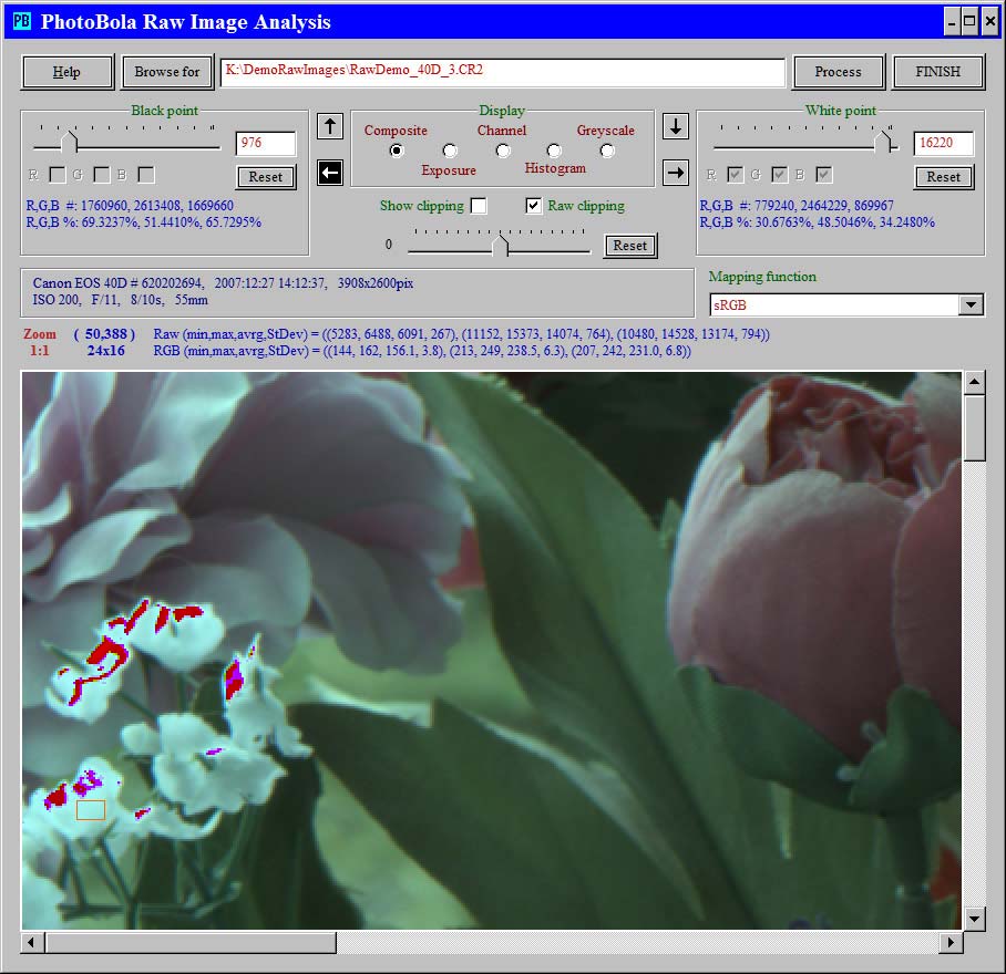
The small flowers at the left edge are supposed to be white. The selection statistics show that the green and blue are virtually on the same level, but the red is much lower. The raw clipping indication is turned on to show, where white balance picked should not be done, for clipped pixels do not show the true proportions between the scenery's colors
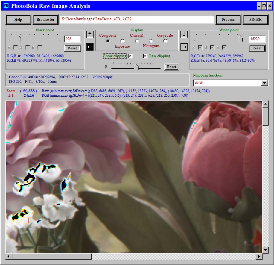
Setting the white balance based on the selected area changes the appearance of the image; particularly, the small flowers became white.
However, the clipping has been increased: where the green and blue was clipped on raw level, now the red is clipped as well (the black spots show, that all three colors clipped)The effect of white balancing on the histogram is demonstrated in the Histogram section.
-
White balancing through selection
-
Lightness
The unlabelled slider is for lightness adjustment. The adjustment can be made at 1/3 EV, 1/2 EV or 2/3 EV points.
The initial position of this slider is usually at null, but in some cases it shows an adjustment, which is indicated in the raw file. Example: Canon 40D images shot with the Highlight Tone Priority (HTP) option start with an adjustment of +1.
The lightness adjustment is a multiplication of the black level adjusted raw pixel values by a factor according to the adjustment. Its effect is comparable to the "Exposure" adjustment in Adobe Camera Raw. The adjustment can be reset to the initial value by clicking on the Reset button under the slider.
The examples at Black point demonstrate the effect of lightness adjustment.
-
Mapping function
Die transformation of the linear raw values from a large numerical range, after black level, white balance and lightness adjustment in RGB values occurs based on some mathematical formulas, often called the "gamma function". Every mapping function results in a different distriobution of the contrast, thereby showing more details in some lightness ranges while less details in other ranges.
The default is the formula defined in sRGB. The best way to learn the differences between these is by trying them out.
Note, that
- choosing sRGB, etc. does not cause any color transformation to that color space, only the related mapping function will be applied,
- the mapping induces clipping,
- the comparable effect can be achieved in raw processors by different contrast settings.
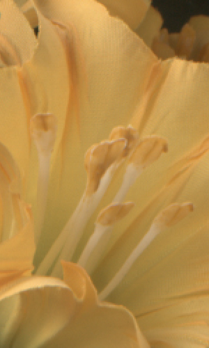
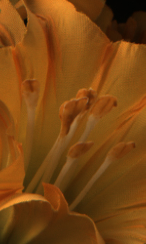
The left side image was created by sRGB mapping, while the right side with linear mapping.
The linear mapping shows that there are lots of details, which can be enhanced in the raw conversion
Modified: 2008-01-29